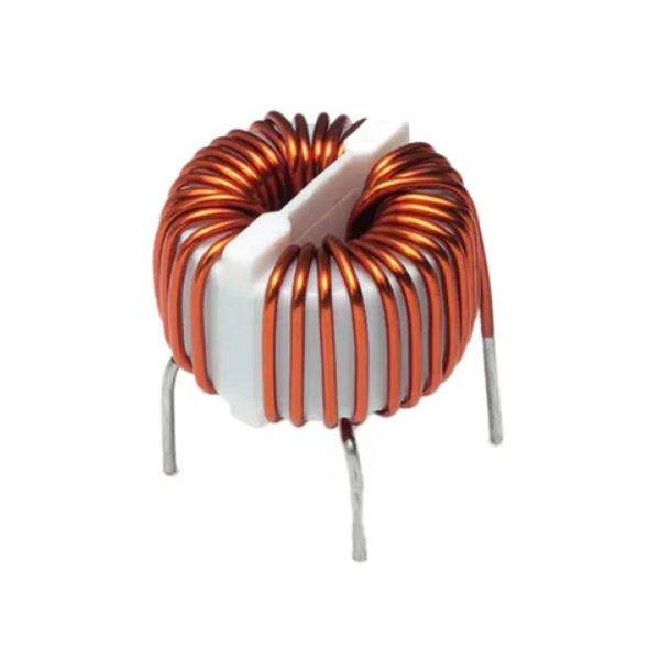
Common mode choke

What's the Common mode choke?
A common-mode (CM) choke is a special application of chokes where it is used to act upon a common-mode signal. These chokes are useful for suppression of electromagnetic interference (EMI) and radio frequency interference (RFI) frequently introduced on high current wires such as on power supply lines, which may cause unwanted operation. Reducing this noise is frequently done by using a common mode choke - two parallel coil windings on a single core. Common mode chokes allow differential currents to pass while blocking signals that are affecting both wires. Because the magnetic flux produced by differential-mode currents in the core of a common mode choke tend to cancel each other out, the choke presents little impedance to differential mode currents. It achieves this by the placement of windings such that they generate equal but opposite fields that cancel each other out for differential mode signals. Normally this also means that the core will not saturate for large differential mode currents, and the maximum current rating is instead determined by the heating effect of the winding resistance. On the other hand, common mode currents see a high impedance path due to the combined inductance of the windings that reinforce each other.
CM chokes are commonly used in industrial, electrical and telecommunications applications to remove or decrease noise and related electromagnetic interference.
When the CM choke is conducting CM current, most of the magnetic flux generated by the windings is confined with the inductor core because of its high permeability. In this case, the leakage flux, which is also the near magnetic field emission of the CM choke is low. However, the DM current flowing through the windings will generate high emitted near magnetic field since the windings are negative coupled in this case. To reduce the near magnetic field emission, a twisted winding structure can be applied to the CM choke.
Selection Considerations for Common Mode Chokes
When selecting a common mode choke for a given application, it is important to consider the specific requirements and restrictions of the system for which it is being installed. Gowanda’s common mode chokes are manufactured in a wide range of sizes and designs to suit a variety of use cases. As a general rule, larger chokes are capable of filtering lower frequencies than smaller chokes, making them suitable for equipment that requires more accurate noise filtering, such as AC/DC outlets.
Key factors to consider when selecting a choke are:
- Current Rating: to ensure the part does not overheat within the application
- Impedance vs. Frequency: to ensure it is optimized to attenuate the desired frequencies.
- Isolation Voltage: to ensure it meets board level requirements between the line and neutral phases.
- Safety Isolation: to ensure it meets the safety requirements of the end application.
Common Mode Choke Design
-
- It is typical for the inductance value of a common mode choke to be specified as a minimum requirement, thus insuring the crossover frequency is not shifted too high.
- The frequency range of the interfering signal should be provided in order to allow proper calculation of the attenuation of unwanted signal noise in the design.
- Proper wire sizing is accomplished by specifying the voltage and current levels across, and passing through, the common mode choke.
Common mode choke filter, line inductor, and differential choke designs vary widely in terms of power rating, inductance, voltage level (low to high), operating frequency, size, impedance, bandwidth (frequency response), packaging, winding capacitance, and other parameters.
Applications
Common mode chokes are commonly used to reduce or eliminate electromagnetic interference (EMI) in industrial applications that require a steady and reliable current without interruption. Typical electrical and electronic devices that may use common mode chokes include:
- Audio/Visual (AV) signaling equipment
- Conveyors and elevators
- Electrical Ballasts
- HVAC systems
- Industrial Tool Drives
- LED Lights
- Medical Equipment
- Oil & Gas Control Systems
- Robotic Equipment
- Switching Regulators
- Switch Mode Power Supplies
- Train Signaling Systems
- Variable Frequency Drives (VFDs)