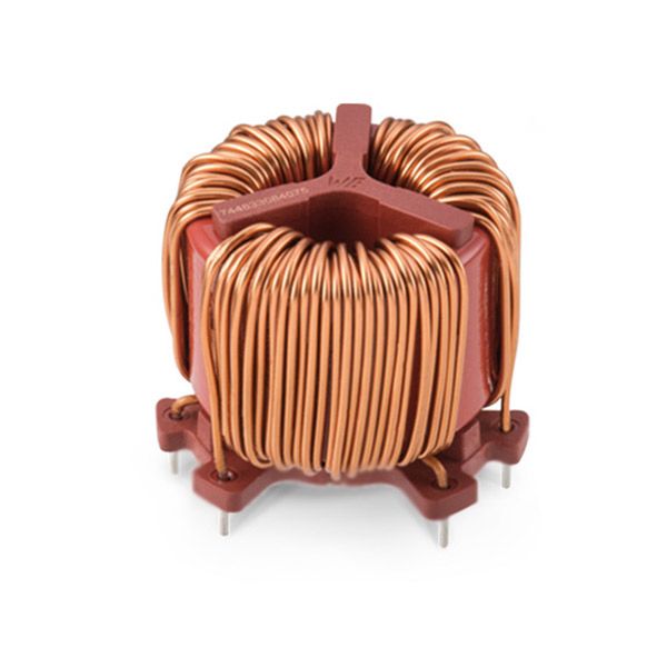
Three-Phase common mode choke

What's the Three-Phase common mode choke?
HIGH-POWER applications require a three-phase conversion of the electric energy. In particular, three-phase PWM converters have increased their market share due to clear advantages over other technologies. On the other hand, PWM converters present some side effects mainly due to the pulsed waveforms with rich spectral contents and very short transient times. Thus, they typically require input filters to comply with the electromagnetic compatibility (EMC) requirements, and three-phase filters present a large demand from the industry.
In this context, three-phase common-mode (CM) inductors find a large application in areas such as adjustable-speed drives, UPSs, renewable energy, process technology, battery charging for electric vehicles, power supplies for IT, future more electric aircrafts, and others. In 1971, a three-phase version of the CM choke was presented, along with the main advantages of this type of construction in suppressing the CM propagated noise. Different methods can be applied to model a CM inductor, ranging from very simple analytical models to the characterization of the inductors based on the in-circuit measurements. In this paper, the models that can be used to design a CM filter inductor are analyzed. The physics of a three-phase CM inductor is explained, and equivalent circuits are derived based on previous literature. The models take into account the core material characteristics and the geometrical configuration of the inductor. The calculation of the leakage inductance is reviewed, and a new model is introduced. Relevant magnetic core saturation issues and, in particular, the mechanisms of local magnetic core saturation are explained. The use of a high switching frequency enables the reduction of the passive component volume, and it is the driving factor for the current increase, in the power density of power converters. It is expected that this growth continues. Thus, the design of volume optimized components becomes very important. For the CM inductors, this motivates the research of accurate models and improved circuit topologies and the utilization of high-performance materials. With this objective, a comparison among the available core materials is performed, with emphasis on material characteristics for filter application. Design issues such as leakage inductance and thermal models for wound toroidal inductors are analyzed, and a novel method for the selection of core materials is proposed for the design of the volume minimized CM inductors.
Selection Considerations for Common Mode Chokes
When selecting a common mode choke for a given application, it is important to consider the specific requirements and restrictions of the system for which it is being installed. Gowanda’s common mode chokes are manufactured in a wide range of sizes and designs to suit a variety of use cases. As a general rule, larger chokes are capable of filtering lower frequencies than smaller chokes, making them suitable for equipment that requires more accurate noise filtering, such as AC/DC outlets.
Key factors to consider when selecting a choke are:
- Current Rating: to ensure the part does not overheat within the application
- Impedance vs. Frequency: to ensure it is optimized to attenuate the desired frequencies.
- Isolation Voltage: to ensure it meets board level requirements between the line and neutral phases.
- Safety Isolation: to ensure it meets the safety requirements of the end application.
Common Mode Choke Design
-
- It is typical for the inductance value of a common mode choke to be specified as a minimum requirement, thus insuring the crossover frequency is not shifted too high.
- The frequency range of the interfering signal should be provided in order to allow proper calculation of the attenuation of unwanted signal noise in the design.
- Proper wire sizing is accomplished by specifying the voltage and current levels across, and passing through, the common mode choke.
Common mode choke filter, line inductor, and differential choke designs vary widely in terms of power rating, inductance, voltage level (low to high), operating frequency, size, impedance, bandwidth (frequency response), packaging, winding capacitance, and other parameters.
Applications
Common mode chokes are commonly used to reduce or eliminate electromagnetic interference (EMI) in industrial applications that require a steady and reliable current without interruption. Typical electrical and electronic devices that may use common mode chokes include:
- Audio/Visual (AV) signaling equipment
- Conveyors and elevators
- Electrical Ballasts
- HVAC systems
- Industrial Tool Drives
- LED Lights
- Medical Equipment
- Oil & Gas Control Systems
- Robotic Equipment
- Switching Regulators
- Switch Mode Power Supplies
- Train Signaling Systems
- Variable Frequency Drives (VFDs)